How to model a curtain panel roof on the space frame structure like above?
First of all, based on the "Metric Curtain Panel Pattern Based.rft", create an adaptive family under Curtain Panels family category.
Then, create a Model In-Place family under the Mass family category for the required roof shape.
Choose the required surface of the Mass and apply the Pattern as the divided surface before you replaced with the loaded Adaptive Curtain Panel family.
The rigid frame of the roof can be modelled with the Model In-Place with sweep.
The rigid panel can be modelled with the Structural Beam Systems and perimeter framing and support framing can be modelled with the Structural Trusses. The mast modelling may need void form mass.
After adjusting the size and visibility control of the panel and members instance parameters of each adaptive curtain panel family the completed Curtain Panel roof with space frame structure are shown below.
BCA has released the CORENET X Implementation Plan together with the CORENET X Code of Practice (COP) where the IFC-SG requirements are defined in details.
The industry was informed the phased onboarding of new projects and existing onto CORENET X to make the necessary plans and preparation well ahead of the implementation dates.
The summary of the key dates and requirements are shown below.
The Code of Practice ( COP) is intended to help industry practitioners in understanding how to prepare multi-agency regulatory submissions across the key submission gateways in CORENET X.
The Code of Practice includes recommended procedures and good practices to address common Building Information Modelling (BIM) issues at general project collaboration level (e g multi disciplinary project set up, geo referencing) and specific details that vary from firm to firm today.
This Code of Practice complements the IFC SG Resource Kit (https://go.gov.sg/ifcsg), which provides technical templates and help resources from key proprietary BIM software for the generation of IFC SG models.
To ensure the regulatory information can be captured and exported to IFC, the information must first be incorporated in the BIM model and exported to IFC.
IFC allows for customization of properties and object types to the existing IFC entities. While most regulatory information will be represented in existing international IFC standards, some "localization" will need to be carried out to capture selected information unique to the Singapore context.
This localized IFC data model that is developed based on the IFC standard to address local regulatory needs is termed as IFC-SG.
In collaboration with BCA, Autodesk has launched a new IFC-SG interoperability tools which will help industry professional populate and export IFC-SG more easily in Revit.
Start from Revit 2020.2, the clip of the Project Base Point
is not available and the Project Base Point is unclipped with the Startup
Location which is now visible and called Internal Origin.
By Default, the Internal Origin, the Project Base Point and the Survey Point are placed in the same location.
If we look Singapore survey system, it is not possible to type in the coordinates directly into unclipped Project Base Point. Since the Project Base Point cannot place more than 10 miles (16 kilometers) from it's Startup location, while moving the Project Base Point, you would receive the following error:-
Moving the Project Base Point together with Internal Origin is important as we are moving the model around the site while the Survey Point is acting as a real-world relation to the Revit model.
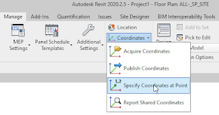
If you want to set the Project Base Point to the known
Boundary Station Point given by your surveyor in 2020.2.2 and later versions, go
to Manage > Coordinates > Specify Coordinates at Point.
Select the Project Base Point in order to move it to the selected Boundary Station Point.
From the Specify Shared Coordinates dialog, fill in
the Northing and Easting values of selected Boundary Station Point
given by the Surveyor.
After specifying Shared Coordinates, you will notice
that the Project Base Point is moving away from the Survey Point together with the
Internal Origin as shown below example.
If your project has 2-storey unit type, the default BCA’s CDS schedule and calculation would show exceeded TNO value which should be 5 as maximum.
It would calculate wrongly for the required area and volume as because of total TNO.
In order to get the combining area, merging the two rows in Revit is impossible.
However, you can add the following additional parameters and formulae to get the combined value.
Rename existing parameter “TNO” to “TNO (1-Level)” before you create new “TNO” parameter as number instead of integer format.
The following formula will be true if the unit has 2 levels.
if(Net Unit GFA % = 1, [TNO (1-Level)], (if(Net GFA < 45 m², 2, if(and(Net GFA < 75 m², Net GFA > 45 m²), 3, if(and(Net GFA < 140 m², Net GFA > 75 m²), 4, 5)))) / 2)
Saving the DWG/DXF Export Setup Setting to a text file
is no longer an option in Revit 2012 and above versions; the settings are
retained/saved in the Revit project file. If you need to copy these settings
between projects, you can use “Transfer
Project Standards” command.
Instead of doing the above process you may wish to create the DWG/DXF Export Layer Standard test file based on your organization practice. For that case please click HERE to download Singapore standard CP83 layer mapping file and open in Notepad application for editing if your office don't have Revit Architecture 2011 version. (In Revit Architecture 2011, use the Export Layers tool to create a custom layer mapping file.)
After you edited mapping values as desired (by entering new Projection or Cut value under appropriate category), save as the settings as a new layer mapping file under your office network drive.
In Modify
DWG/DXF Export Setup dialog box, click Create New Export Setup and name ABC Company
Standard.
By
default, you can choose one of the four standards to use but you have to choose
the fifth option Load setting from file
from the Load layers from standards
list. From Load Export Layer File dialog box, browse to your newly created
Export Layers Standard text file, and click OK. Enjoy!
Most of the time we have to submit amendment
plan submission to BCA/FSSD while we are waiting for URA’s reply to re-submit for GFA
regularisation. Since amendment submission needs to show only additional SGFA
calculation, we need to keep our current Gross Area Scheme and have to create
New Gross Area Scheme separately. In this case, we are not recommended for creating
New Rentable Area Scheme which is not related with GFA or SGFA calculation. The
first step of Step-by-step procedure as per below is the trick:-
Create temporary Design Options
·From Area and
Volume Computations dialog box, under Area Schemes tab, click “New”. Select Area Scheme Type dialog box will
open and you can create New Gross Area Scheme by selecting Create Gross Area
Scheme type.
·For Name, enter a name for the new area scheme and for
Description, enter a description of the new area scheme, and then click OK.
·Now you can delete unwanted Design Options.
·Create Area plans views based on newly created area
scheme and level
·Apply BCA_SGFA view template for each view
·Create SGFA color scheme and place a legend by using
Color Fill Legend tool. To assign SGFA color scheme to the view, from Choose
Space Type and Color Scheme dialog box, choose SGFA color scheme and click
OK.
·Later you can delete this SGFA Color Fill Legend if
you like to replace with new SGFA Color Legend from the Legends view
·For this amendment submission, we can easily create
Area Schedule which is similar to built-in SGFA schedule.
Suggestion
If
we like to get individual area for “Other areas not included in GFA
computation” which will allow you to comply with BCA-BP-SGFA document, we can add
an additional shared parameter.
·Create and add text type parameter with named “Other
areas not included in GFA computation” as an instance shared parameter under
“Other” group parameter for Areas category.
·Write a description as shown above for each Area
according to Annex 1 of BCA-BP-SGFA document.
·Create an additional color scheme, for instance
SGFA_BREAKDOWN by using “Other areas not included in GFA computation” parameter
for the colouring.
·Place the SGFA_BREAKDOWN legend by using Color Fill
Legend tool. Assign SGFA_BREAKDOWN color scheme to the view, then we will get a
colorful area plan view and no need to create a sheet to add an additional
legend view.
·Keep original SGFA schedule and create additional
schedule to comply with BCA-BP-SGFA document as follow:-
Optional
If we like to hide unnecessary Area Boundary lines in the URA
area plan view, we can assign a workset to those Area Boundary lines and turn
off the visibility for that workset for workshare enabled projects.
As per BIM Submission Guideline for Architectural
Discipline, Gross Floor Area (GFA) for URA
submission need to summarize in a table format with GFA breakdown.
For
all the GFA breakdowns, multiple instances are collapsed onto a single row for
each level and it is difficult to check the GFA breakdown on the area plan
view separately. Even you select the value under particular Breakdown column to
display them on the area plan view,
Revit will select and show all the instances of the same row.
In order to select and display per breakdown in the area plan
view, follow the steps below.
On
the Sorting/Grouping tab of the Schedule Properties dialog, you need to specify
additional sorting option for rows in this schedule.
Ensure
Itemize every instance is turned
off.Add one of the breakdown areas in
the 3rd row under the Sorting/Grouping tab and set to
Desending.
If
you select the particular breakdown area cell in the area schedule, Revit will
show you every instance of that breakdown area on the respective level of area
plan view.
For
above example, you will see additional one row for each level in the area
schedule since we only have 2 breakdowns.